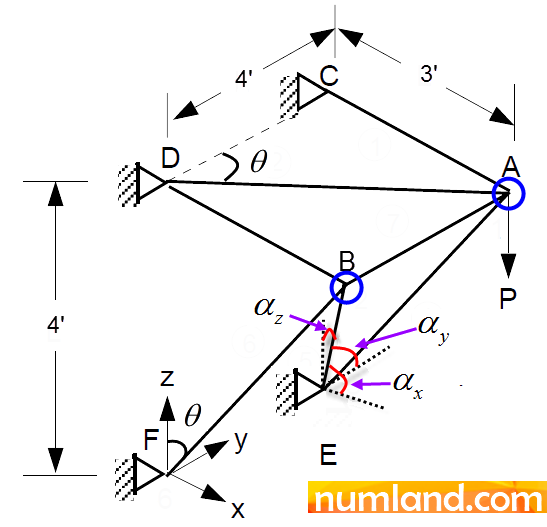
Consider the simple, pin-jointed truss with 7 members shown in the figure. The support points (C, D, E, F) are gripped into a vertical wall, so that, they can translate in no direction. We are willing to calculate the axial stress produced in the member AD by the vertical load of 1000 lb symbolized by P, which is applied at joint A. To verify the result, also, it will be compared with the precise analytical solution mentioned in reference [1]. All members have the same cross-sectional area of 1 in2, and the same modulus of elasticity of 30×106 psi. Furthermore, the dimensions are given in foot.
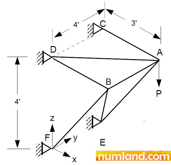
Modeling the problem:
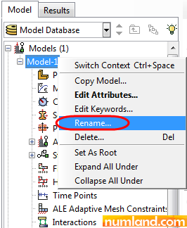
Firstly, rename model from Model-1 to 3D truss using one of methods presented as following:
1- From the menu bar, follow this path:
Model > Rename > Model-1
2- As shown in Figure 2, right click on Model-1 in model tree and select Rename.
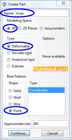
Click on icon ![]() (Create Part) and fill the window opened like Figure 3. As the truss we are evaluating is in 3D space, so, we have selected the item 3D in Modeling Space zone. In order to model trusses, it is usually simpler if we define truss joints by Points, and then, connect them by lines or truss elements. Finally, close the window by clicking on Continue button.
(Create Part) and fill the window opened like Figure 3. As the truss we are evaluating is in 3D space, so, we have selected the item 3D in Modeling Space zone. In order to model trusses, it is usually simpler if we define truss joints by Points, and then, connect them by lines or truss elements. Finally, close the window by clicking on Continue button.
In Prompt Area, the point coordinate, by default, is (0,0,0). Accept this coordinate and press the Enter key. This leads to creating the part, which is a Reference Point, and representing it in 3D space. To create the other joints of truss, we can use Datum Point tool. So, go through the following steps in menu bar:
Tools> Datum
Figure 4 displays which items must be selected in the opened window.
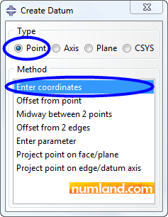
As the unit of given modulus of elasticity is ![]() , we must consider length of elements and forces in Inch and Pound, respectively. Hence, the coordinates of 5 remained points, which are brought in table 1, have been given in inch and these numbers must be put in Prompt Area. This leads to represent 6 points totally in Viewport.
, we must consider length of elements and forces in Inch and Pound, respectively. Hence, the coordinates of 5 remained points, which are brought in table 1, have been given in inch and these numbers must be put in Prompt Area. This leads to represent 6 points totally in Viewport.
Table 1: Coordinate of truss joints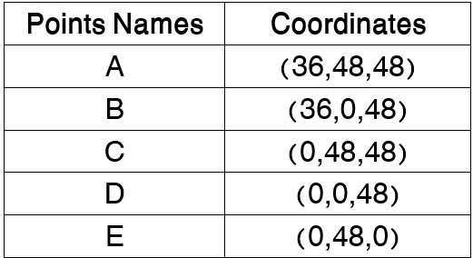
After that press Esc key to exit from Datum point command. To see all the points created in previous step, click on icon ![]() (Auto-Fit View). In addition, you can rotate the model using icon
(Auto-Fit View). In addition, you can rotate the model using icon ![]() (Rotate View) in View Manipulation toolbar. Using this, make the view of model like one you see in Figure 5 to ease selecting points.
(Rotate View) in View Manipulation toolbar. Using this, make the view of model like one you see in Figure 5 to ease selecting points.
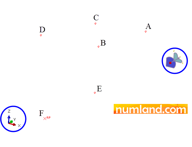
Before continuing the modeling process, save the view you made in prior step as we need it in the next steps. To do this, click on icon ![]() (Save View) placed in Views Tools which is shown in Figure 6.
(Save View) placed in Views Tools which is shown in Figure 6.

Selecting the items in opened window, illustrated in Figure 7, click on OK button. This assigns the concerned view on icon ![]() (Apply User 1 View) and by clicking on this icon, in every other module, you can see the model through saved orientation.
(Apply User 1 View) and by clicking on this icon, in every other module, you can see the model through saved orientation.

After the steps mentioned above, create the members of truss, going through this steps:
Shape > Wire > Point to Point
In window of Create Wire Feature shown in Figure 8, lines and spline curves can be drawn utilizing Polyline and Spline options, respectively. In addition, Chained wires draws connected lines and icon ![]() (Add) adds another line (wire) to the model.
(Add) adds another line (wire) to the model.
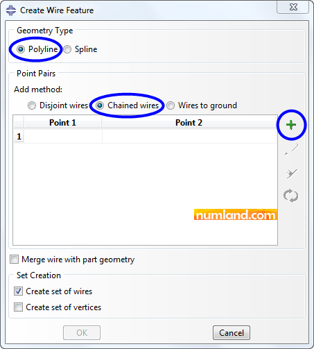
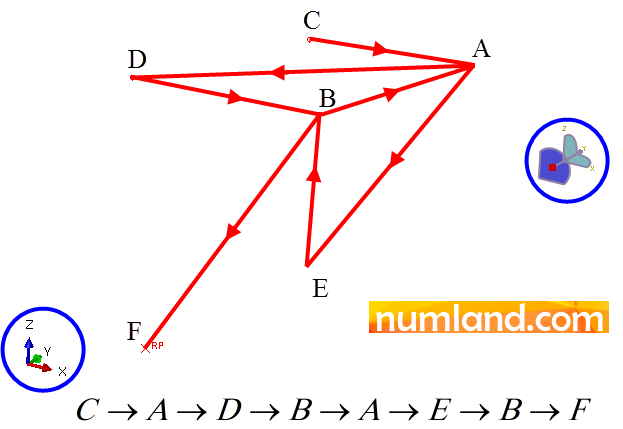
Noticing Figure 8, click on icon ![]() (Add), then, select the points seen in Viewport in 7 orders you see in Figure 9.
(Add), then, select the points seen in Viewport in 7 orders you see in Figure 9.
After all, click on Done button in prompt area. The opened window must appear like Figure 10, then.
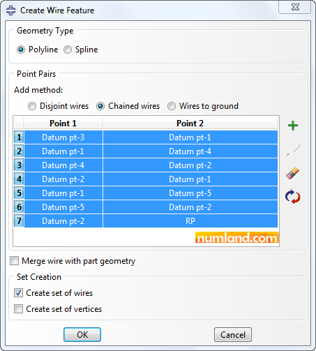
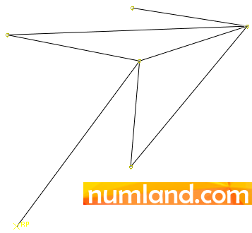
Confirm the information and press OK button. You will see the aimed truss as displayed in Figure 11.
Material property definition:
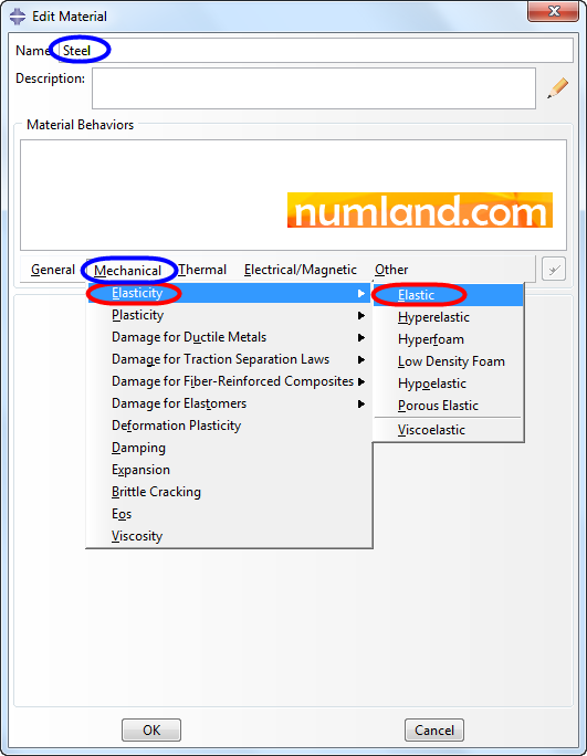
As it is mentioned, the material of truss elements is steel. In order to define related parameters go to Property module and choose icon ![]() (Create Material). Name the material Steel and select the items which Figure 12 demonstrates to define the Modulus of Elasticity.
(Create Material). Name the material Steel and select the items which Figure 12 demonstrates to define the Modulus of Elasticity.
Fill opened window same as what you see in Figure 13. Remember that the Modulus of Elasticity unit has been considered in ![]() . In addition, the sign e in most engineering programs means “10 to the power of a number”. To put that in perspective, here 30e6 symbolizes 30×106.
. In addition, the sign e in most engineering programs means “10 to the power of a number”. To put that in perspective, here 30e6 symbolizes 30×106.
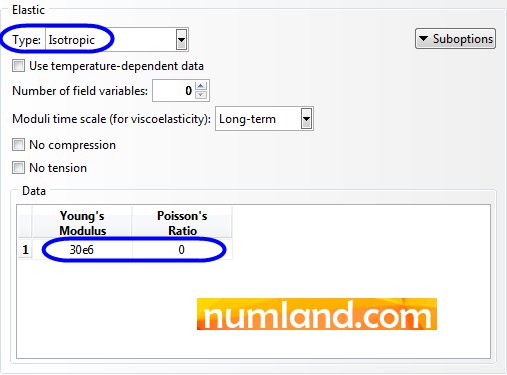
Finally, click on the button OK to save the elastic features of the material.
Note 1To assign the material and geometry properties to the model, firstly, you need to make Section. This tool, in the Property Module, is a command to determine the material in different parts of the model. For example, consider a bar which is made from half steel and half aluminum. In such case you need to define two sections which are contains two different materials, steel and aluminum. Besides, when you are defining sections related to truss elements, the value of cross-section area will be asked. Considering this, in case of different cross-sections, it is needed to define a variety of sections with diverse area magnitudes even if you have one material. |
To create a section click on icon ![]() (Create Section), then, in opened window choose Beam and Truss items. Finally, continue as Figure 14 shows. The name of section could be changed to find it easily in the next steps.
(Create Section), then, in opened window choose Beam and Truss items. Finally, continue as Figure 14 shows. The name of section could be changed to find it easily in the next steps.
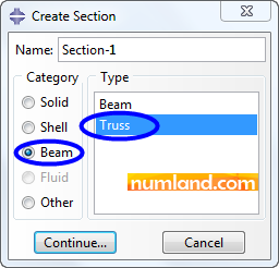
After that, in Edit Section window select the material which is defined in previous step and enter the value of cross-sectional area (1 in2) as shown in Figure 15.
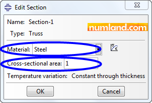
Note that elements of current truss we are modeling have same material and one cross-sectional area. Therefore, defining one section suffices.
To specify defined section to the truss members click on icon ![]() (Assign Section). After that, select all parts of the truss and then finish the process clicking on button Done. Click OK button of Edit Section Assignment window, so that, the steel material will be assigned to all members. To see the geometry of truss visually do as following:
(Assign Section). After that, select all parts of the truss and then finish the process clicking on button Done. Click OK button of Edit Section Assignment window, so that, the steel material will be assigned to all members. To see the geometry of truss visually do as following:
View > Part Display Options
Choose Render beam profiles, then, click OK. See Figure 16.
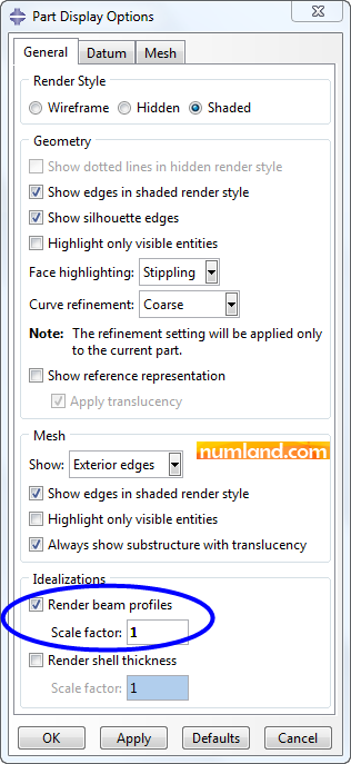
The result will appear as it is seen in Figure 17. Note that the Scale factor has been specified 1 and this leads to show the truss with the exact geometry. To change the proportion of cross sectional area you can adjust this parameter.
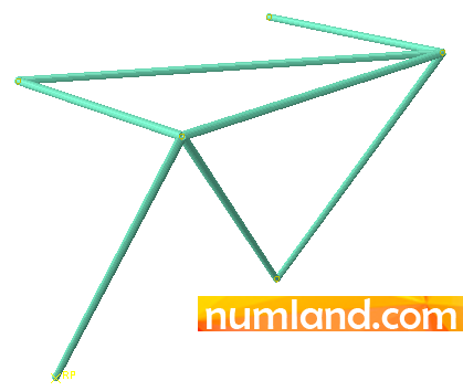
Assembling the truss in Assembly module:
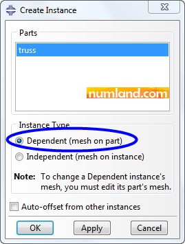
Enter module of Assembly and select the icon ![]() (Instance Part). As you can see in Figure 18, choose the item Dependent (mesh on part) and click on OK button. By this, the truss created in Part module enters in Assembly environment.
(Instance Part). As you can see in Figure 18, choose the item Dependent (mesh on part) and click on OK button. By this, the truss created in Part module enters in Assembly environment.
Note 2In case that we have a part which is positioned several times in different positions of Assembly environment, it is possible to mesh the part once and use the same pattern of meshing, multiple times. That is when Dependent (mesh on part) option helps. Obviously, when having one part used once we prefer to choose the item Independent (mesh on instance) to mesh the part in Assembly level, directly. Here, however, we did choose the Dependent to mesh the part in Part level while we could do it in Assembly level, to distinguish differences of these options. |
Before you keep doing, save the whole model using this procedure:
File > Set Work Directory…
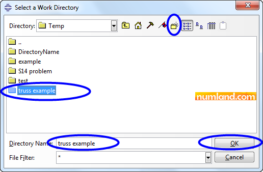
Then, you will see an opened window which asks specifying a directory to put the files in. Click on icon ![]() (Select). Choose a folder utilizing the tools pointed out in Figure 19. In this case make a new folder by use of icon
(Select). Choose a folder utilizing the tools pointed out in Figure 19. In this case make a new folder by use of icon ![]() (Create new directory) and name it truss example, next, click on OK button.
(Create new directory) and name it truss example, next, click on OK button.
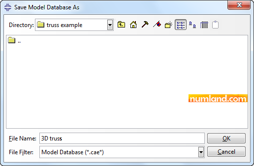
Now using File > Save As save the model, in the specified folder, with the name of 3D truss, see Figure 20.
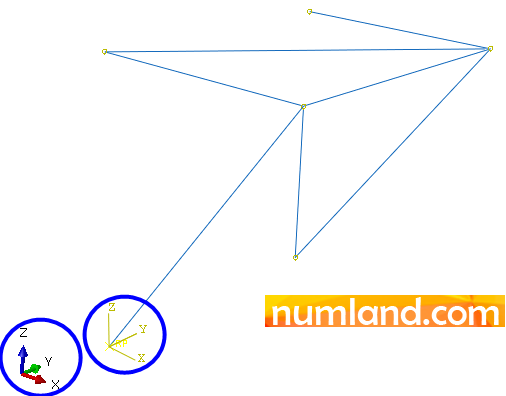
Before you continue, click on icon ![]() (Apply User 1 View) to show the truss in the view represented in Figure 1. By doing this, you will see the truss and its coordinate system in Assembly module (Figure 21). Looking the model through this view facilitates applying loads and boundary conditions.
(Apply User 1 View) to show the truss in the view represented in Figure 1. By doing this, you will see the truss and its coordinate system in Assembly module (Figure 21). Looking the model through this view facilitates applying loads and boundary conditions.
Define the static analysis:
Enter the Step module, then, click on icon ![]() (Create Step). In opened window which is named Create Step configure the items as Figure 22 illustrates and close the window selecting Continue button.
(Create Step). In opened window which is named Create Step configure the items as Figure 22 illustrates and close the window selecting Continue button.
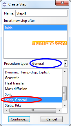
Another window will appear up; accept all default values and click on OK button.
Note 3Note that in Edit step window, value of 1 is specified for the parameter of Time period while it would not make difference if any other number was inserted, because in this kind of static analysis, which value or direction of force does not vary by the time, considering the parameter of time is meaningless. Furthermore, in this window the item Nlgeom stays off as current problem is linear and we are not observing nonlinear effects of displacements or large deformations on the model, otherwise, it must have been turned on. |
Applying loads and defining boundary conditions:
Enter Load module. Using the tools provided in this module, you need to fix the points C, D, E, and F, which are pointed out in Figure 23, in all directions to simulate supports which fix the truss statically.
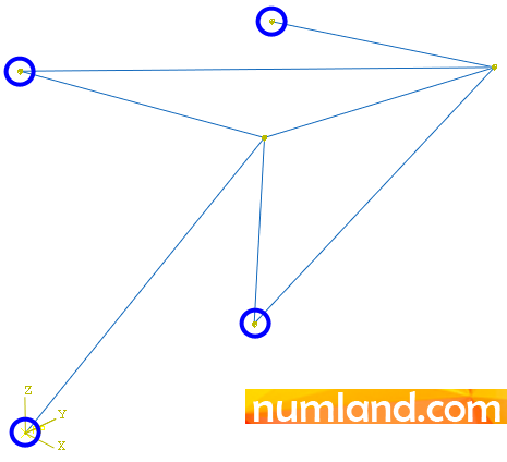
Note that the Reference Point F (with coordinate of (0,0,0)), which was created by the time you had made the part, may get wrong with the end of related element (FB) and selecting this point will fail the simulation. In fact, to define boundary conditions you need to select endpoints of truss members or their vertices. To do this, you need to apply vertices filter by use of Selection tool from toolbox; See Figure 24.
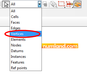
Now, click on icon ![]() (Create Boundary Condition) and select the items specified in Figure 25 and choose Continue button.
(Create Boundary Condition) and select the items specified in Figure 25 and choose Continue button.
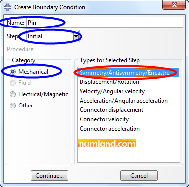
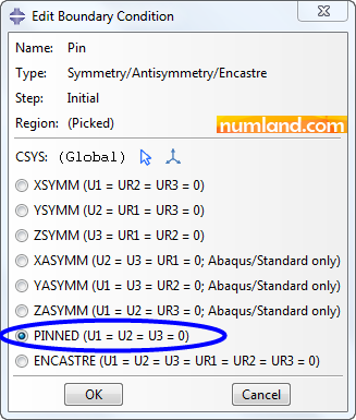
Press and keep the Shift key, then, select the points shown in Figure 23 and finally, click on Done. After this, like Figure 26, a window with name of Edit Boundary Condition appears. Choose PINNED option and push OK. This causes that all degrees of freedom of displacement related to selected points stays at zero. At the end, you will see the symbol of boundary conditions placed on the support points.
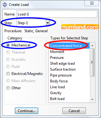
To apply concentrated force of 1000 lb, indicated with P, choose the icon ![]() (Create Load). In opened window, then, select Step-1 from the list next to the Step and choose the items like what pointed out in Figure 27.
(Create Load). In opened window, then, select Step-1 from the list next to the Step and choose the items like what pointed out in Figure 27.
After clicking Continue you will be asked to select the point on which force applies. Choose point A, circled in Figure 28, then, Done button.
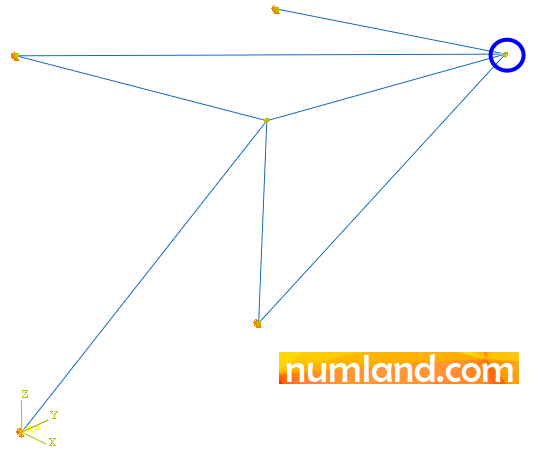
Figure 29 shows how to fill Edit Load window. After confirming, a yellow arrow will emerge on point A with reverse direction of Z.
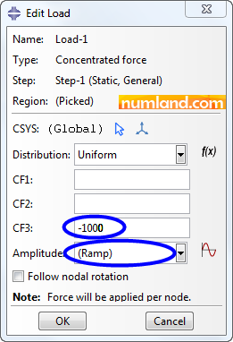
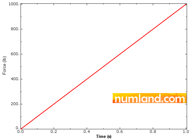
Note 4Take notice that in Edit Load window, the option Ramp means that load, in numerical solving, will increase linearly from zero to the maximum value which is determined 1000 here. So, firstly (when time is 0s) force is assumed 0 lb and at the end (Time = 1s) its value reaches to 1000 lb as you see in figure a.
|
Meshing the model:
Enter the Mesh module. By the time we had inserted the part in assembly environment, we decided that the assembly would stay Dependent on the part. As we said, it means we need to create meshes on part level not the assembly. For this reason, first of all in meshing step put the Object option on Part as shown in Figure 30. You will see elements cross-sections same as what you saw in Part module.

Note 5Remember that every member of the truss must contain 1 element in meshing. If not, the answers being taken from numerical solver will not converge because truss elements in FEM observes displacement degree of freedom not rotation types; so, they cannot tolerate shear forces. Considering this and as truss members behave the same, each member behaves like 1 truss element in FE analysis. |
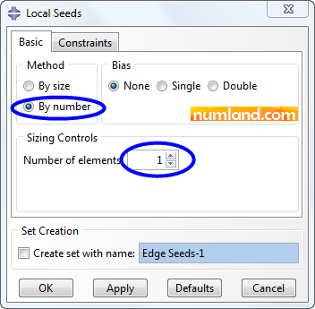
To create 1 element on each member click on icon ![]() (Seed Edges), next, select all truss members, by dragging the mouse and clicking Done button. Then, in window of Local Seeds, which is displayed in Figure 31, value the item Number of elements 1 and push OK. Some pink squares emerge on the vertices of members, indicating each member will mesh by 1 truss element.
(Seed Edges), next, select all truss members, by dragging the mouse and clicking Done button. Then, in window of Local Seeds, which is displayed in Figure 31, value the item Number of elements 1 and push OK. Some pink squares emerge on the vertices of members, indicating each member will mesh by 1 truss element.
Finally, choose the icon ![]() (Mesh Part) to generate meshes on truss members. A message in Prompt Area asks to confirm meshing all parts. Answer Yes. By this, meshing will be done; however, you cannot see meshes on the model. To make them visible, disable the item related to rendering beam profiles from View > Part Display Option. Doing this causes that color of elements changes to cyan. As you know, in FE analysis, choosing appropriate element is significant. Accordingly, it is needed to determine truss element as element type of FE model. To do this, click on icon
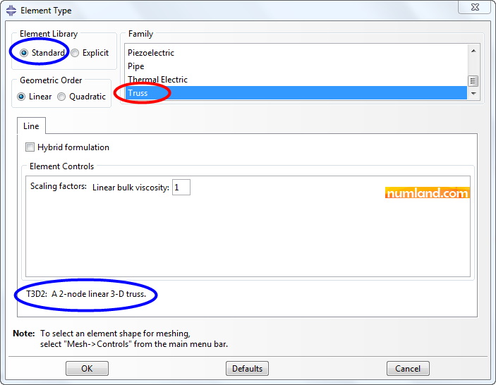
(Mesh Part) to generate meshes on truss members. A message in Prompt Area asks to confirm meshing all parts. Answer Yes. By this, meshing will be done; however, you cannot see meshes on the model. To make them visible, disable the item related to rendering beam profiles from View > Part Display Option. Doing this causes that color of elements changes to cyan. As you know, in FE analysis, choosing appropriate element is significant. Accordingly, it is needed to determine truss element as element type of FE model. To do this, click on icon ![]() (Assign Element Type), then, select all parts of model, by dragging the mouse and clicking on Done button. Like Figure 32, a window with name of Element Type comes up containing Family box. Take the Truss item which specifies the type of element. Take it into consideration that Beam was selected by default and this item is utilized when we are evaluating a problem involves beam elements. Another point is in section of Element Library, where the option Standard has been chosen. This means Abaqus/Standard will solve the equations. Moreover, a nickname which indicates type of selected element has been demonstrated at the bottom of window. For instance, here the element is named T3D2 by Abaqus. T, 3D and 2 stand for, respectively, Truss type element, three-dimensional space and the element has 2 nodes.
(Assign Element Type), then, select all parts of model, by dragging the mouse and clicking on Done button. Like Figure 32, a window with name of Element Type comes up containing Family box. Take the Truss item which specifies the type of element. Take it into consideration that Beam was selected by default and this item is utilized when we are evaluating a problem involves beam elements. Another point is in section of Element Library, where the option Standard has been chosen. This means Abaqus/Standard will solve the equations. Moreover, a nickname which indicates type of selected element has been demonstrated at the bottom of window. For instance, here the element is named T3D2 by Abaqus. T, 3D and 2 stand for, respectively, Truss type element, three-dimensional space and the element has 2 nodes.
Analyzing the problem:
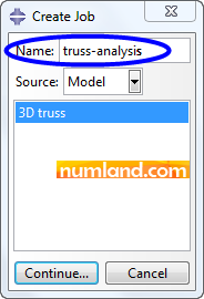
In order to set the equations and solve them, enter the Job module and select the icon ![]() (Create Job). As shown in figure 33, name the analysis truss-analysis in opened window and Continue.
(Create Job). As shown in figure 33, name the analysis truss-analysis in opened window and Continue.
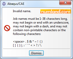
Note 6Note that when you state a name for job, do not use characters like space, slash, dot, brackets, etc. otherwise you will face an error shown in Figure a:
|
In Edit Job window accept all default conditions. Now, click on icon ![]() (Job Manager) and push the button Submit, pointed out in figure 34. This leads to solver launches solving the problem.
(Job Manager) and push the button Submit, pointed out in figure 34. This leads to solver launches solving the problem.
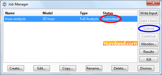
Notice the Status column in Job Manager window (Figures 35). This will change to Submitted, Running and Completed, in order.
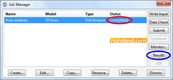
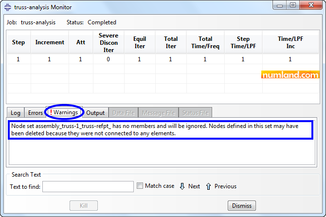
Note 7If you click on Monitor in Job Manager window, you can observe what happens when solving procedure is ongoing. For example, open the tab Warning, which is identified by a red ! sign. In this part, an error message says there is a node separated from other members of model. This node is the Reference Point which was created at first step and the error clarifies that this node is ignored as well as we did when we were defining boundary conditions. Consequently, this error can be neglected.
|
In order to see what obtained from solving the problem click on Results button in Job Manager window. This switches to the Visualization module automatically. Firstly, the shape of truss without any deformation will be displayed. Click on icon ![]() (Apply User 1 View) to see the model in the saved view. To observe deformed shape of truss click on icon
(Apply User 1 View) to see the model in the saved view. To observe deformed shape of truss click on icon ![]() (Plot Contours on Deformed Shape) as you see in Figure 36.
(Plot Contours on Deformed Shape) as you see in Figure 36.
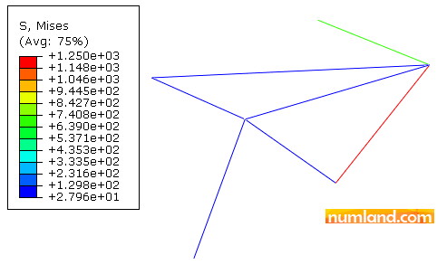
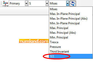
In this matter, outputs like displacements of nodes and stresses in elements can be reported. In case you need these outputs for a specific node or element, using Probe Values tool can help. Concerning this, from list of Field Output, firstly select S11 like what displayed in Figure 37, which stands for axial stress in Truss Elements.
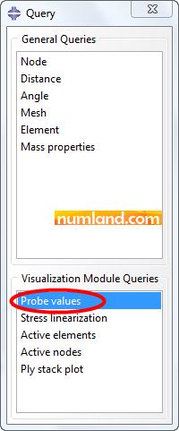
Secondly, click on icon ![]() (Query information) and select Probe values as seen in Figure 38.
(Query information) and select Probe values as seen in Figure 38.
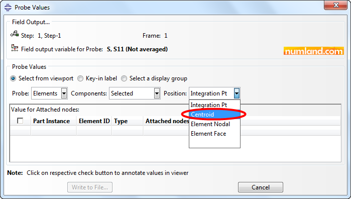
Selecting Probe values brings up a window like Figure 39. As you know, stress in truss members is uniformly distributed and this allows us to measure S11 values from middle of members (truss element). Considering this, select the item Centroid as Position of measurement.
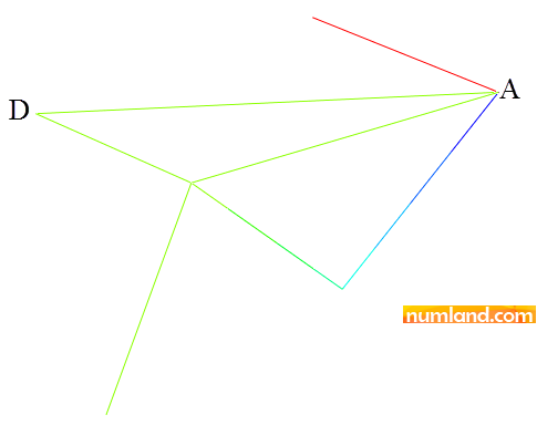
We were supposed to measure the stress of element AD and compare it with the results reported in reference [1]. So, using Probe values tool select midpoint of element AD as marked in Figure 40.
Click on the element to see stress value in Probe values window, which is shown in Figure 41.
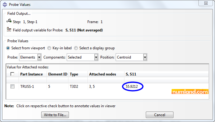
The magnitude of stress, in member AD, obtained from FE analysis (Abaqus), exact solution and result reported in reference [1] can be compared in table 2. Take notice that reference [1] did not mention the stress value precisely; for this reason we solved the problem with analytical equations as well.
Table 2: Magnitudes of axial stress in member AD
As you can see there is a tiny deviation between results obtained from FEA and Analytical Solution. In fact, this happens in all small deformation analysis of trusses and this type of FE analysis is called Direct Method which means the result equals analytical solution output.
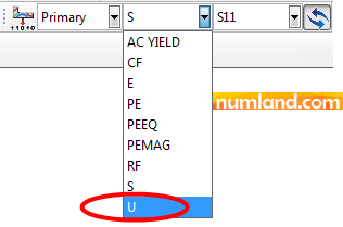
To check displacement of each node using Probe values tool, as displayed in Figure 42, firstly, select U from list of Field Output.
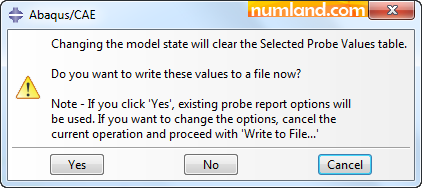
Note that you may face a message of what brought in Figure 43 asking for deleting or saving the information stated in Probe values window.
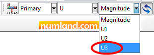
You can measure node displacements in all three directions. In this case, critical point in term of displacement is the point A, especially in Z direction. Accordingly, we select item U3 from list of Field Output (Figure 44).
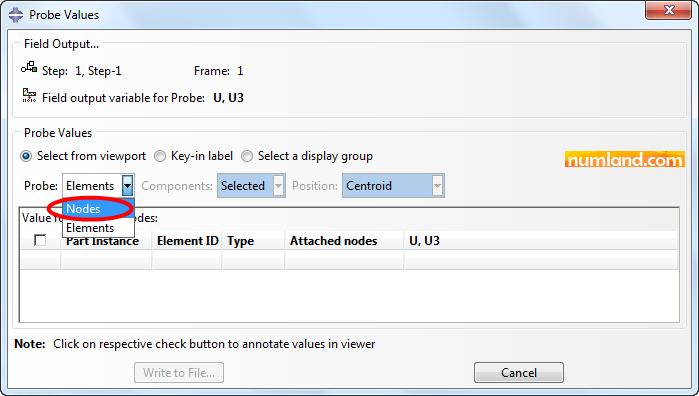
In order to see the reports related to nodes, in Probe Values window put the option of Probe on Nodes same as items that Figure 45 shows.
Now, pick the node on which the force was applied (Point A). This represents the value of -0.0037698 in Probe Values window which implies movement of point A, in reverse direction of Z.
The outputs can be reported and saved in a file with extension of rpt, going through the steps mentioned below.
Report > Field Output
At the beginning, save stresses values which produced in the elements. To do this, as Figure 46 displays, take the options under Variable tab in opened window.
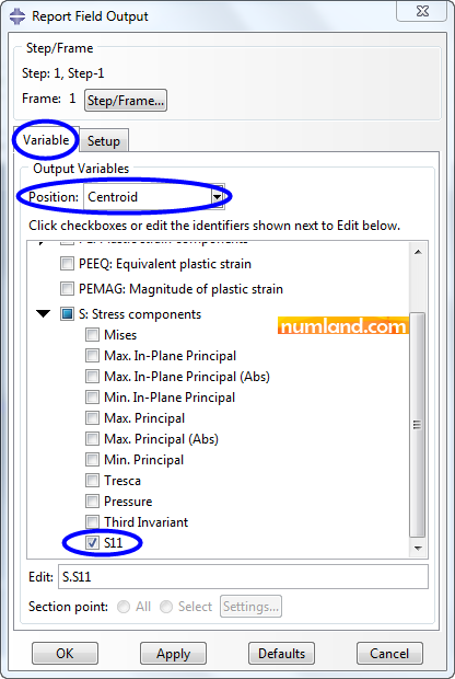
As mentioned above, the option Centroid states outputs of elements midpoint and S11 symbolizes axial stress for truss elements (generally, wire shaped elements). Note that for some other types of elements, S11 stands for stress in X direction of global coordinate system. Noticing Figure 47, go to Setup tab and configure the items as displayed. The point is that if Append to file is enabled, the results will be write in prior file which might have been created before; however, if there was no file, this option would not make any difference.
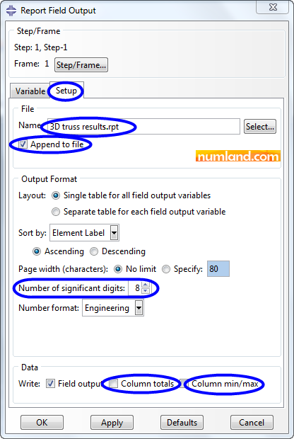
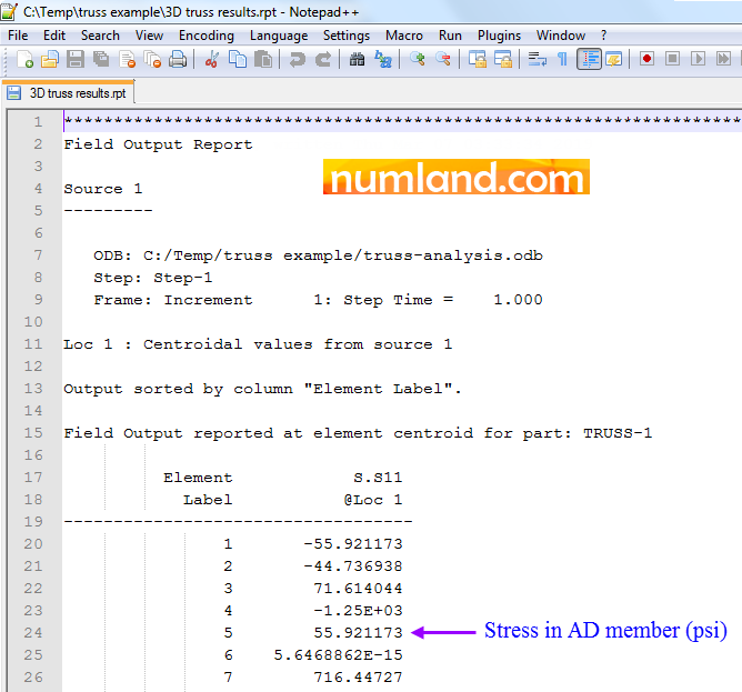
The file created can be observed using Notepad or Notepad++. Figure 48 shows Notepad++ representing information in this file. Consider that in this report stresses are given in psi.
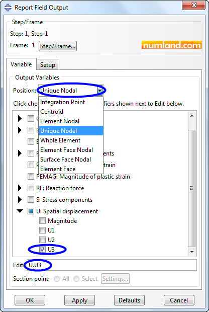
Using same process, you can take the outputs related to displacements in U3. To do this, firstly, as Figures 42 and 44 illustrate select the item of U3, then, choose the options displayed in Figure 49. Using the item Unique Nodal makes it possible to see outputs of displacements on nodes. Take notice that, here, stress results have not been marked.
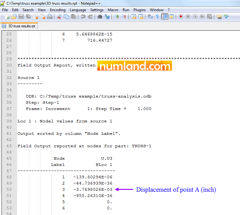
Hitting on OK button, considered results will be added to the rpt file because Append to file was activated. Figure 50 presents these results after the stress results generated in previous step.
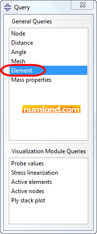
As you saw in Figures 48 and 50, the information in rpt file have been given based on numbers of elements or nodes. To find these numbers especially numbers of element AD and node A click on icon ![]() (Query information). By this, Query window comes up, then, select the item Element, as pointed out in Figure 51 and finally, select the element AD among the other members.
(Query information). By this, Query window comes up, then, select the item Element, as pointed out in Figure 51 and finally, select the element AD among the other members.
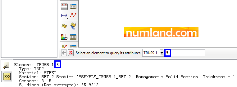
The information related to this element will be presented in Prompt Area and Message Area which is displayed in Figure 52. As you see, there exist some other useful information like Type, Material, Section, etc.
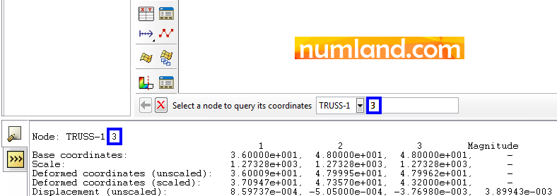
In addition, selectin the item Node in Query window, makes us able to observe Nodes information. Here, as we wanted select the node A. This gives this node information in the same areas, as Figure 53 shows.
Analytical Method:
In this section, Castigiliano’s method, which is a method of analytical determining forces and displacements, will be utilized to calculate stress in AD element analytically. The equations are written in the software Maple. Regarding this, we write the equilibrium equations in directions of X, Y, Z for two points, A and B. This gives us 6 equations with 7 variables, so that, the 7th equation will be derived based on Castigiliano’s method. To inform more you can see the reference [1] or other Strength of Materials books. Like what seen in Figure 54, to write equilibrium equations of each point, consider forces components of related element.
The equations of each node written in three directions have been presented in Figures 55 to 57. Equations 1 to 4 give angles, while, equations 5 to 7 are developed according to equilibrium in the node A.
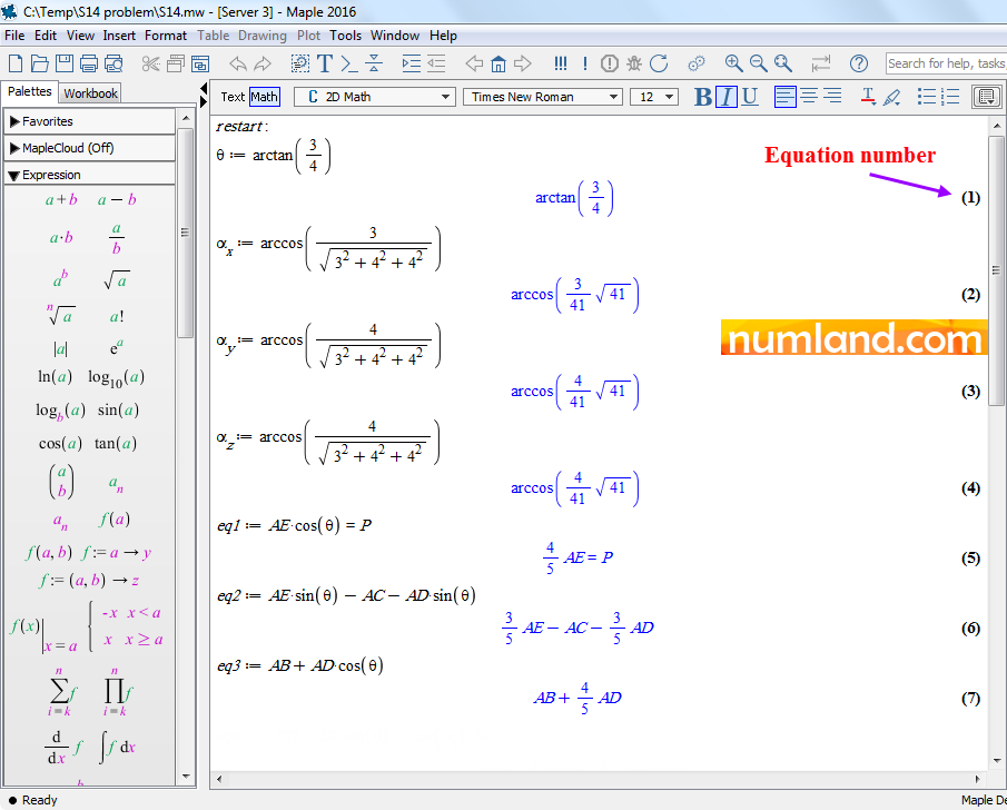
Equations 8 to 10 having displayed in Figure 56, are equilibrium equations of node B. After all, in equation 11, the variables in 6 equations are transformed to variable of AD element. Then, strain energy of entire system has been calculated in equation 12, depending on the force we are looking for (AD). Based on Castigiliano’s method, strain energy has been differentiated with respect to the force in AD element, seen in equation 13. As a result, the unknown force can be determined from the force P which was 1000 lb (equation 14). Finally, forces in elements AD and AB are calculated in equations 15 and 16, respectively.
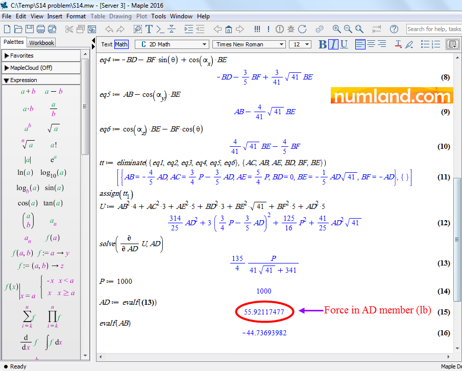
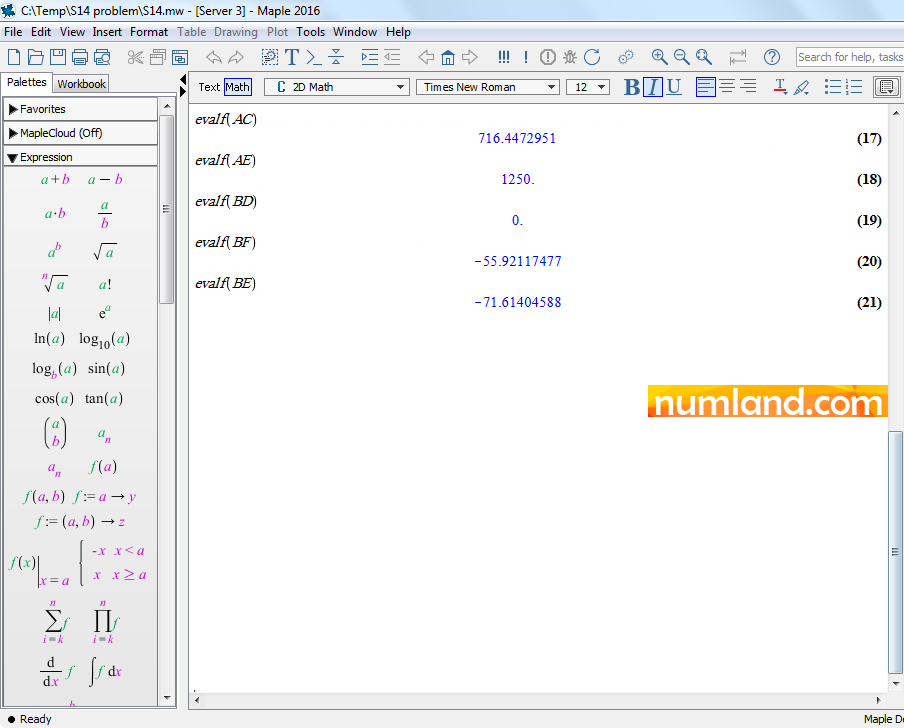
Furthermore, Figure 57 presents amounts of forces in other elements. As mentioned in the problem, cross-section of all elements have area of 1 in2. Considering this, stress in elements can be obtained using the equation below:
This means stress in the element AD is 55.92117477 psi as mentioned in Table 2.
Exercise:
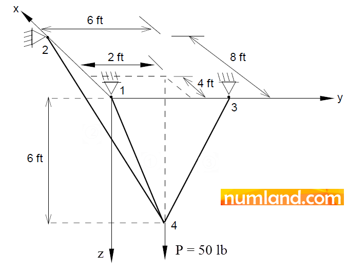
Considering Figure 58, a force of 50 lb is applied on a truss. A concreted wall fixes endpoints of all members. This means degrees of freedom related to the supports are gripped in all directions. Modulus of Elasticity and cross-sectional area of all elements are 30×102 and 1 in2, respectively. Determine stresses in the elements 1-4, 2-4 and 3-4 [2]. Note that this truss is statically determinate and you can earn analytical results by writing simple equilibrium equations.
Note 8Take notice that in this problem you cannot create the geometry of truss in one step as we did in Figure 9. Because the elements are separated and it is impossible to select the nodes one after another. This makes you select the icon |
Magnitudes of Stress in each element are presented in Table 3.
Table 3: Stress magnitudes in questioned members![]()
References:
[1] Timoshenko, S. P. and Young, D. H. “Theory of Structures,” end Ed., McGraw-Hill, New York, 1965, pp. 330-331.
[2] Beer, F. P., and Johnston, E. R., Jr., “Vector Mechanics for Engineers: Statics and Dynamics,” McGraw-Hill Book Co., Inc. New York, 1962, p. 47.

Be the First to Comment!